

Views: 0 Author: Site Editor Publish Time: 2026-07-01 Origin: Site


Rushing a new mold directly into mass production without a rigorous trial phase leads to severe financial and operational consequences. High scrap rates, sudden tool failure, and missed production deadlines happen when manufacturers bypass proper validation. The core problem lies in the gap between theoretical mold design and physical manufacturing reality. Even precision-engineered molds behave unpredictably under the intense thermal and mechanical stresses of an active extrusion blow molding machine.
To bridge this gap, a standardized mold trial checklist serves as the only empirical method to validate tooling. This structured approach establishes a reliable process window, ensuring scalable, defect-free production. By systematically isolating variables, manufacturers diagnose root causes of defects and optimize the process before committing to high-volume runs.
Validation Over Speed: A structured trial prevents premature wear and costly rework by identifying mechanical and thermal imbalances before high-volume runs.
Process Window Mapping: Establishing the upper and lower limits of temperature, pressure, and cycle time is critical for long-term production stability.
Pinch-Off and Cooling Dominance: In blow molding, pinch-off integrity and cooling channel efficiency dictate both part quality and unit economics.
Data-Driven Sign-Off: Moving from T1 (first shot) to mass production requires documented, verifiable data on wall thickness, shrinkage, and functional performance, not just visual approval.
Establishing what constitutes a successful trial is the first step in the validation process. A baseline must be defined, focusing on continuous operation without flash hang-ups, achieving target cycle times, and meeting precise dimensional tolerances. Without clear success criteria, evaluating the trial's outcome becomes subjective and prone to error. You need hard data to confirm the tool is ready for the floor.
The trial progression typically follows defined T-stages. Each stage serves a specific diagnostic purpose, preventing compounding errors. A phased trial approach effectively mitigates risk by isolating variables. By systematically testing the machine, material, and mold independently, technicians accurately diagnose the root cause of any defects.
Trial Stage | Objective | Key Deliverables |
|---|---|---|
T0 | Initial fit and function without material | Mechanical clearance, safety interlock verification, dry cycle success |
T1 | First functional parts | Initial parison programming, basic pinch-off check, gross defect identification |
T2/T3 | Optimization and dimension correction | Cooling optimization, wall thickness mapping, dimensional adjustments |
T4 | Pre-production run | Process capability data (Cp/Cpk), finalized parameter sheet, continuous run validation |
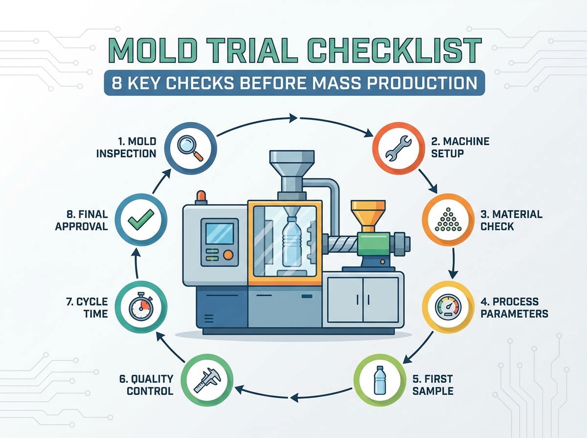
Before mounting the tool, confirm that the blow molding mold dimensions match the final CAD specifications. Conduct a thorough cleanliness and corrosion audit. Verify that all cavity surfaces, slide actions, and parting lines are clean, dry, and free of rust-preventive compounds, corrosion, or pitting. Document the actual tool dimensions against design drawings to establish a true baseline.
Proper calibration of the machine prevents uneven clamping force, which causes premature mold wear or flash. Verify that the extruder screw and head tooling, including the die and mandrel, are clean and correctly sized for the target parison. Confirm that all water, air, and hydraulic lines are securely connected. Pressure-test these connections for leaks before initiating any mechanical movements.
Inspect cavity surfaces for polishing quality, corrosion, or machining marks.
Verify the presence and placement of all alignment pins, guide bushings, and wear plates.
Ensure parting lines are sharp and undamaged to prevent flash.
Check that all moving components are properly lubricated according to specifications.
Calibrate platen parallelism using dial indicators or laser alignment tools.
The objective of the dry run is to verify safe, interference-free operation before introducing plastic into the system. Cycle the mold at low pressure to check guide pin engagement and platen alignment. Gradually increase the clamping force to full tonnage, monitoring for any signs of strain or misalignment. Listen for abnormal noises that indicate binding.
Test the actuation of all moving components, such as blow pins, stripper plates, unscrewing mechanisms, or moving inserts. Ensure smooth operation without binding or galling. Verify the timing, stroke, and force of mechanical ejector systems. Parts must release cleanly without physical scuffing, distortion, or deep ejection marks.
Confirm that machine safety gates and mold protection sensors function correctly. These interlocks prevent catastrophic tool damage in the event of a malfunction. A successful dry run guarantees that the mechanical systems are robust and ready for material processing.
Achieving a stable, repeatable parison drop that matches the mold cavity profile dictates the success of the entire run. Monitor the melt temperature closely to ensure consistent flow and prevent parison sag or melt fracture. Adjust the extrusion speed and die gap to achieve the correct parison length and target part weight.
Map the wall thickness distribution along the length of the parison using Weight Distribution System (WDS) programming. This accommodates complex mold geometries and varying blow ratios. Proper programming ensures material is distributed exactly where needed for structural integrity, preventing thin corners or heavy bottoms.
Conduct controlled, low-pressure or short-duration blowing trials to observe the progressive inflation path of the parison. This partial-blow balance test verifies balanced inflation and identifies potential weld-line or structural weak points before full-pressure expansion occurs. It shows exactly how the plastic stretches inside the cavity.
Ensuring clean separation of flash and strong weld lines is a primary objective during the trial. Inspect the pinch-off edges on the mold for proper width and angle. They must cut the plastic cleanly without being overly sharp, as excessively sharp edges cause weak welds that fail under pressure. Dull edges result in thick flash that is difficult to trim.
Evaluate the bottom and neck pinch-offs on the trial parts. Conduct immediate destructive testing, such as squeeze tests or drop tests, to check for splitting or weakness at the weld lines. Strong weld lines are essential for the structural integrity of the final product.
Verify that the flash breaks away easily and cleanly, whether manually trimmed or processed through an automated deflashing station. Ensure the remaining tail or handle vestige is minimal and does not leave sharp protrusions or stress-concentration points that could compromise safety or aesthetics.
Pinch-Off Defect | Probable Cause | Corrective Action |
|---|---|---|
Weak Weld Line (Splitting) | Pinch-off edge too sharp or mold too cold | Increase pinch-off land width; increase mold temperature locally |
Thick, Un-trimmable Flash | Pinch-off edge worn or insufficient clamp tonnage | Re-machine pinch-off edges; verify clamp pressure |
V-Notch at Weld | Poor material flow into the pinch-off zone | Adjust parison programming to push more material to the tail |
Accurate neck finishes and the prevention of trapped air defects depend on proper blow pin alignment and venting. Check the concentricity and depth of the blow pin entry. Misalignment causes uneven neck thickness, poor sealing surfaces, and potential leakage in the final product. The blow pin must strike dead center every time.
Inspect the trial parts for trapped air marks, surface pitting, or incomplete feature formation, often referred to as short shots. These defects indicate inadequate venting within the mold cavity. Air must escape as fast as the plastic expands.
Verify that mold vents, including parting line vents, sandblasted surfaces, or porous inserts, are adequately sized. They must evacuate air rapidly during inflation without allowing the melt to flash into the vent channels. Clean vents regularly during the trial to prevent clogging from resin off-gassing.
Maximizing heat transfer achieves the fastest stable cycle time. Measure the water flow rate and temperature drop across all cooling circuits. Identify any blocked or restricted channels that could cause uneven cooling and subsequent part warpage. Use flow meters on every circuit, not just the main manifold.
Confirm that water channels do not cross-leak into air vents, guide bushings, or mechanical slides. Such leaks cause cosmetic blemishes, rust, and mechanical failure over time. Use a thermal camera on the ejected parts and the open mold faces to identify hot spots, particularly around the neck and pinch-off areas.
Incrementally reduce cooling time until part deformation, such as warpage or shrinkage, occurs. This establishes the absolute minimum cycle time threshold, allowing for optimal production efficiency without sacrificing part quality. Record the exact water temperatures and flow rates required to maintain this cycle.
Meeting structural requirements while minimizing resin usage requires precise wall thickness control. Cut the trial parts at critical cross-sections, such as corners, handles, and bases. Measure wall thickness using ultrasonic gauges or calipers to ensure compliance with design specifications.
Evaluate areas with high blow ratios, such as deep draws, for excessive thinning. Thin walls in these areas compromise the structural integrity of the part and lead to failure during use. You must push material into these deep pockets using the WDS.
Correlate thickness variations back to parison programming or tooling adjustments. Optimize material distribution by adjusting the die and mandrel shaping or refining the WDS profile to ensure uniform strength and minimal material waste. Shaving a few grams off the part weight without losing strength yields massive savings over a long run.
Validating that the part meets all end-user specifications is the final quality gate. Conduct a thorough visual inspection for aesthetic defects such as die lines, flow marks, gels, carbon specks, warpage, or surface scratches transferred from the mold cavity. The surface finish must match the approved sample.
Allow parts to condition for 24 to 48 hours to account for post-molding shrinkage before measuring critical dimensions against the 2D drawing tolerances. Immediate measurement yields inaccurate results due to ongoing thermal contraction. Plastics shrink significantly as they cool to room temperature.
Perform application-specific functional evaluations. These tests include drop impact testing, top-load crush testing, leak detection, and closure torque testing to ensure the part performs reliably in its intended environment. A bottle that looks perfect but leaks at the cap is a failure.
Ensuring the process is robust enough for continuous mass production requires establishing a wide process window. Intentionally vary key parameters, such as melt temperature, blow pressure, and cooling time, to find the upper and lower limits where acceptable parts can still be produced. A narrow process window means constant operator intervention.
Run a continuous sample of 50 to 100 shots at the optimized center-line process. Measure critical dimensions to calculate process capability and repeatability, ensuring the process remains stable over time. You want a Cpk greater than 1.33 for critical dimensions.
Compile a structured trial run-off report that documents the exact process progression, modifications made, and the resulting part qualities across each trial iteration. Record the finalized parameter sheet, which becomes the immutable baseline for operators during mass production.
Pushing for ultra-fast cycle times using aggressive cooling or chilled water presents significant trade-offs. While it increases output, it raises the risk of condensation, mold sweating, and premature wear on moving parts, potentially leading to increased maintenance costs and downtime. Sweating molds ruin surface finishes and cause rust.
Address the reality of T1 trials by acknowledging that expecting perfection on the first shot is unrealistic. Establish a framework for deciding whether a defect requires a physical mold modification, such as welding and re-machining a pinch-off, or if a simple process adjustment will suffice. Do not cut steel until you have exhausted process solutions.
Highlight the risk of conducting trials with prime virgin resin if the mass production run will utilize a high percentage of regrind or post-consumer recycled material. Material variability significantly impacts shrinkage, flow behavior, and final part performance. Always run the trial with the exact material blend planned for production.
Transitioning from trial to mass production demands strict adherence to the established baseline.
Lock in the finalized parameter sheet and prohibit unauthorized adjustments on the floor.
Implement a preventative maintenance schedule based on the wear patterns observed during the T4 run.
Train operators specifically on the visual defect identification and troubleshooting steps mapped out during the trial.
Set up automated dimensional checks for the first 10 shots of every shift to catch process drift early.
A: The T0 trial verifies the mechanical fit and function of the mold without introducing plastic. It ensures all moving parts, guide pins, and ejectors operate smoothly and safely under full clamping tonnage.
A: Parison programming controls the wall thickness distribution along the length of the extruded plastic. It ensures complex geometries and deep draws receive adequate material for structural integrity without wasting resin.
A: Pinch-off edges determine the strength of the weld lines and the ease of flash removal. Improperly designed edges cause weak welds that split under pressure or leave thick flash that is difficult to trim.
A: Trapped air defects occur when mold vents are inadequately sized, blocked by resin off-gassing, or poorly placed. This prevents air from escaping rapidly as the plastic inflates against the cavity walls.
A: Plastic parts undergo significant post-molding shrinkage as they cool completely. Conditioning for 24 to 48 hours ensures measurements accurately reflect the final dimensions after thermal contraction has stopped.
A: A process window defines the upper and lower limits of operating parameters, such as temperature, pressure, and cycle time, within which acceptable parts can be consistently produced without defects.